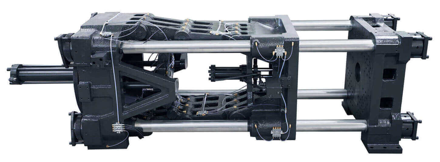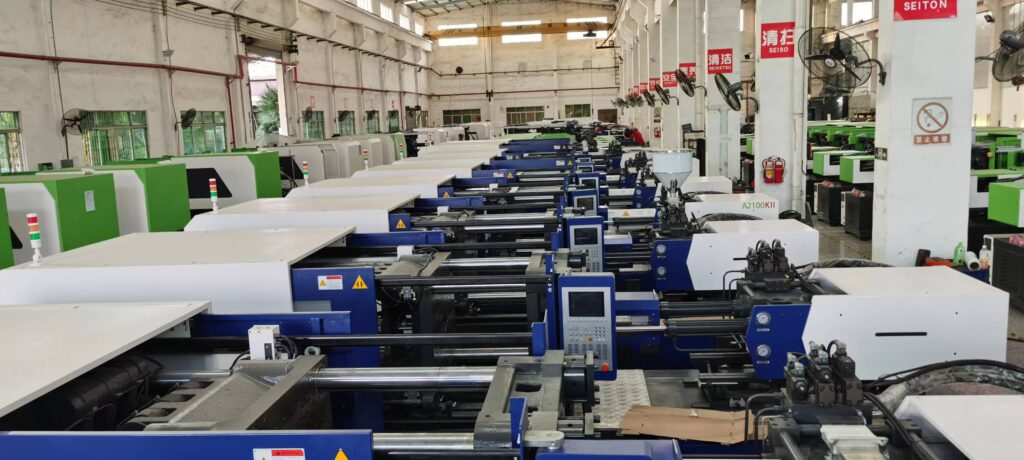
All movements in the injection molding process, whether hydraulic or electric, generate injection pressure. Appropriate control of the required injection molding pressure produces a great product with good quality. The injection pressure regulation and metering system is on the hydraulic injection molding machine, and all movements are performed by the oil circuit responsible for the following operations:
1. Screw rotation in the plasticizing stage.
2. Slider feeder (the nozzle is close to the nozzle bushing).
3. Axial movement of the injection screw during injection and pressure holding.
4. Close the base material on the injection rod until the toggle rod is fully extended or the piston mold clamping stroke is completed.
5. Start the ejection table of the assembly ejector to eject the components.

On full electric injection moulding machines, all movements are performed by brushless synchronous motors with permanent magnets. Rotary motion is converted into linear motion by ball bearing screws, which have always been used in the machine tool industry. The efficiency of the entire process depends in part on the plasticizing process, in which the screw plays a crucial role.
The screw must ensure that the material is melted and homogenized. This process can be adjusted by means of back pressure to avoid overheating. The mixing elements must not generate excessive flow rates, otherwise, polymer degradation will result. Each polymer has a different maximum flow rate, and if this limit is exceeded, the molecules will stretch and the polymer backbone will break. However, the focus remains on controlling the forward axial movement of the screw during injection and holding.
The subsequent cooling process, including intrinsic stress, tolerances and warpage, is important to ensure product quality. It’s all about mold quality, especially when it comes to optimizing cooling runners to ensure effective closed-loop temperature regulation. The system is completely self-contained and does not interfere with mechanical adjustments. Mold movements such as mold closing and ejection must be precise and efficient. Velocity profiles are usually employed to ensure accurate approach of moving parts.
The contact maintenance force is adjustable. Therefore, it can be concluded that the product quality is mainly determined by the system that controls the forward movement stage of the screw without considering the energy consumption and mechanical reliability, and the additional conditions are the same (such as the quality of the mold). On hydraulic injection molding machines, this adjustment is accomplished by sensing the oil pressure. Specifically, the oil pressure activates a set of valves through the control panel, and the fluid acts through the manipulator, which is regulated and released.
Injection speed control includes options such as open-loop control, semi-closed-loop control and closed-loop control. Open loop systems rely on a common proportional valve. Proportional tension is applied to the desired proportion of the fluid, which causes the fluid to create pressure in the injection barrel, causing the injection screw to move at a forward speed. The semi-closed loop system uses a closed loop proportional valve. The loop is closed at the location of the closing port, which controls the flow rate of the oil by moving within the valve. The closed loop system closes when the screw translates speed.
A speed sensor (usually a potentiometer type) is used in a closed loop system to periodically detect tension drops. The oil flowing out of the proportional valve can be adjusted to compensate for the speed deviation that occurs. Closed-loop control relies on dedicated electronics integrated into the machine. Closed-loop pressure control ensures uniform pressure during the injection and hold phases, as well as uniform back pressure throughout the cycle.
The proportional valve is adjusted by the detected pressure value, and the deviation is compensated according to the set pressure value. In general, hydraulic pressure can be monitored, but detecting melt pressure in a nozzle or mold cavity is another effective method. A more reliable solution is to manage proportional valves by reading nozzle or cavity pressure readings. Adding temperature detection on the basis of pressure detection is particularly beneficial to process management.
Knowing the actual pressure the material can withstand also helps predict the actual weight and size of the molded part based on set pressure and temperature conditions. In fact, by changing the holding pressure value, more material can be introduced into the mold cavity to reduce part shrinkage to meet design tolerances (including preset injection shrinkage). Near melting conditions, semi-crystalline polymers show large changes in specific volume. In this regard, overfilling the mold will not hinder the ejection of the part.
